Acoustic properties of selected high strength
thermosetting plastic composites at ultrasonic frequencies
David Wuchinich
Director
Modal Mechanics
2012 Ultrasonics
Industry Association Symposium
San Francisco, CA
© 2011 David Wuchinich
Abstract
High strength thermosetting plastic composites
provide static strengths comparable to some metals while having densities
slightly greater than water and an acoustic impedance
comparable to aluminum. To evaluate their use as ultrasonic resonators
measurements were made of their density, extensional sound velocity and elastic
constant. To determine their utility and limitations as ultrasonic horns
operating at substantial displacements and stress their Q was also measured at
stress levels in the range of 50 MPa (7300 psi) at 20 kHz. It was found that
one of these materials, although more costly than metals, may serve well as a
replacement for metal horns for output displacements in the range of 75 microns
(3 mils), peak-peak at 20 kHz, particularly in applications where low weight
and long length is desired.
Introduction
The cyclic fatigue strength of many
thermoplastics is available from a number of sources.[1] However these data were obtained almost
exclusively using bending or torsional strain at
frequencies in the range of 1-10 Hz. Niermac
reported measurements of the Q of polymers at imposed cyclic pressures below 1
atm at a frequency of 1500 Hz.[2] The properties of
thermo and thermosetting plastics at substantial strain at ultrasonic frequencies
have been sparsely evaluated. Menges
and Barbari studied cyclic loss in polycarbonate and polypropylene at 20 kHz at
strains in the range of 0.002.[3] Earlier, Mason evaluated, at a frequency of
about 18 kHz, the Q and fracture strain of Bakelite[4]. His apparatus is shown in Figure 1. His acoustic arrangement is followed in this
report.
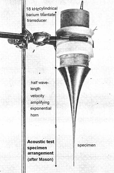
Figure 1 – Mason’s test apparatus for
measurement of acoustic loss
Because of ease with which modern thermosetting
composite plastics, which offer static strengths substantially larger than
thermoplastics, can be formed and cured into complex shapes they are an
attractive candidate for mass production as ultrasonic horns. A comparative evaluation
of their dynamic modulus and acoustic loss at ultrasonic frequency at strains
of practical interest where their use, for example, in producing cavitation
initiated sono-chemical reactions for consumer and industrial products, may assist
their consideration for use in such applications. This report relates an evaluation, in the regime
of practical interest, of three such composites: G9, consisting of a woven fiberglass fabric
impregnated with a melamine resin; G11, fiberglass cloth impregnated with an
epoxy resin; unidirectional carbon fiber impregnated with a bisphenol epoxy
resin[5]. For purposes of reference, an evaluation was
also made of unfilled polycarbonate for comparison with Menges’ report made
under similar frequency and strain conditions.
Test
Method
Computation of the elastic modulus of the
materials was made by measurement of the frequency of their first free-free
flexural vibration[6]. Although this method can be readily employed
for metal samples in lengths of as little as 15 cm (6 in.), composites, having
a much lower Q, require much longer sample lengths, on the order of 100 cm, so
that the duration of vibration is sufficiently long to permit measurement.
By suspending the sample at each of two nodes
of vibration, located 22.4 percent of the sample’s length from each end, and
striking its center the frequency is read from an oscilloscope or frequency
meter connected to a microphone held in proximity. Figure 2 illustrates test arrangement.
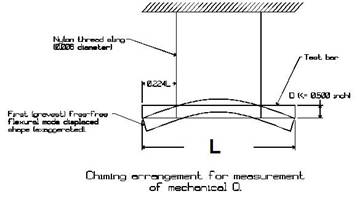
Figure 2 – Measurement of elastic
modulus by chiming
If f is the measured frequency of vibration, l
and D the sample’s length and diameter, the extensional sound velocity, c, can
be computed as[7]:
 (1)
(1)
From weight and dimensional measurements the
density, ρ, can be
found and thus the elastic modulus, Y, computed as
![]() (2)
(2)
Table 1 summarizes the measurement
results. For purposes of comparison,
the values for 6Al-4V titanium have been included.
Table 1 – Density and Modulus of
test samples
|
Material |
Density,ρ, kg/m3 (lbsf/in3) |
Modulus, Y, GPa (Mpsi) |
Sound velocity,c, m/s (103 in/s) |
|
polycarbonate |
1190 (.043 |
2.5 (0.364) |
1450 (57.2) |
|
G9 |
1850 (.067) |
29 (4.16) |
3700 (145) |
|
G11 |
1990 (.072) |
29 (4.19) |
3800 (149) |
|
Carbon Fiber |
1605 (0.058) |
112 (16.3) |
8400 (331) |
|
6Al-4V Titanium |
4420 (0.160) |
110 (16) |
5080 (200) |
Samples were then cut from stock rod having a
length, ls = c/2f, computed to be equal to
a half wavelength of extensional resonance at 20 kHz. Figure 3 is a photograph of three of the samples.
Note the disparity in lengths between the
samples.
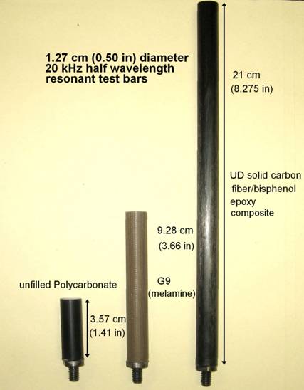
Figure 3 – 20 kHz extensionally
resonant plastic test rods
A 20 kHz piezo-electric transducer equipped
with a 9:1 velocity transforming stepped horn was provided for the tests. This transducer was driven by a power
amplifier whose input was provided by a variable frequency and amplitude
sinusoidal signal generator. A high
frequency watt meter (Clarke-Hess Model 255)[8] was
connected between the power amplifier’s output and the transducer. The schematic test setup is shown in Figure
4.
Note that the watt meter is connected to register only
the power consumed by the transducer and not that as well consumed by the
meter’s current sensing shunt. As such,
it’s reading of real average power delivery to the transducer appears negative.
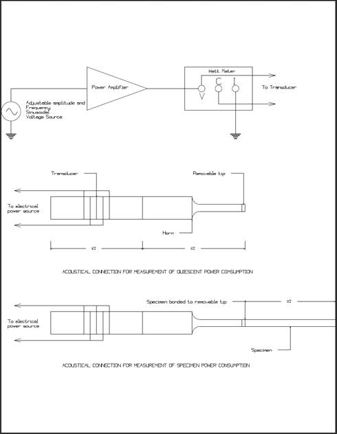
Figure 4 - Electrical and Mechanical test
configuration
Prior to attaching a specimen, the power
consumption of the transducer-horn combination was measured at various
vibration amplitudes, as determined by a 300X microscope equipped with a
calibrated reticule, at the free end of the horn, which contained a removable
tip. The vibration was measured at the
maximum stroke point in microns (mils) peak-peak. The equipment arrangement is shown in Figure
5 with a specimen in place.
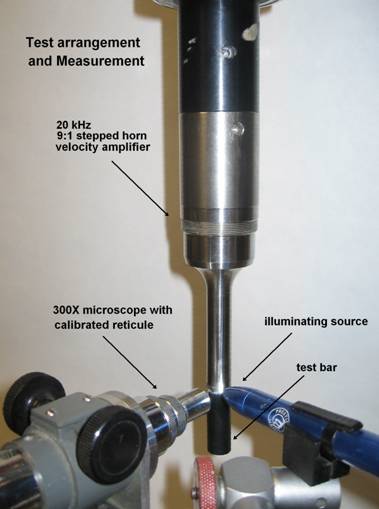
Figure 5 - Vibration measurement and location
The horn with the tip attached was resonant at 20.0
kHz. Following measurement of the power
consumed by transducer and horn, the tip was removed from the horn and bonded
to a sample using Emerson and Cummings Eccobond G909 structural epoxy. This
high strength epoxy cures at 100 oC, a temperature unlikely to
affect the structure of the specimens. The
power consumption at maximum stroke and the resonant frequency was measured for
successive increases in vibration amplitude.
Q is defined as 2π(Energy,
Es, stored in vibration per cycle)/(Energy lost, El, per
cycle of vibration). From the power
measurements, the vibration amplitude, the mass of the sample and the frequency
of vibration, Q can be computed as:
 (3)
(3)
Where m is the mass of the specimen, v is velocity of
vibration of the free faces = 2πfs/2, where s is the peak to peak
excursion, Pt is the power consumption measured with the specimen
attached and Pq the power at
the same excursion measured for the transducer-horn alone and f is the
resonant frequency. With the
substitution, v = 2πf(s/2), s being the peak-peak excursion, made:
 (4)
(4)
This computation assumes that the resonant frequency measured
for the transducer-horn system remains the same when the specimen is attached,
a condition that prevailed within 0.1 percent during testing.
Results
The Q obtained at successively increased excursion in
each of the samples is shown in Figure 6.
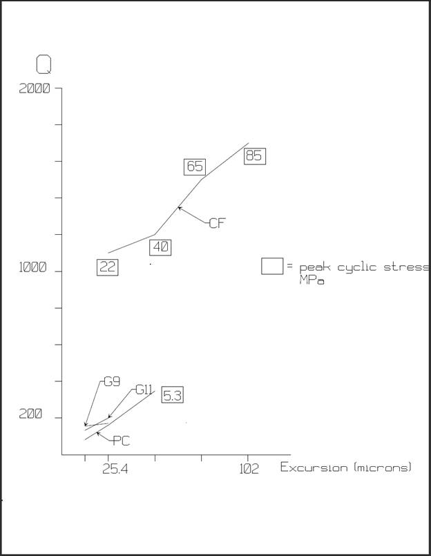
Figure 6 - Acoustic Q vs. resonant
free end excursion
Discussion
The value of Q obtained for polycarbonate is in
approximate agreement with that of 100 obtained by Menges3. Both epoxy composites, G9 and G11, exhibit
similar values which compare rather starkly with those obtained for Titanium of
20,000[9]. Clearly the uni-directional carbon fiber
sample exhibits much lower acoustic loss than either of the fiberglass-epoxy
composites or polycarbonate. The author
has found, however, that polycarbonate is capable of continuously surviving
operation at 20 kHz cyclic stresses of approximately 1.4 MPa (200 psi) if
provision is made, given the low thermal conductivity of plastics compared to
metals, for cooling the material. This
level of stress amounts to an excursion of 15 microns (0.6 mil) in a right
prismatic extensional half wave length resonator.
Because both G9 and G11 exhibit an increased sound
velocity compared to polycarbonate, their half wavelength substantially exceeds
that of polycarbonate. As a result, the
power required to maintain vibration above 50 microns was beyond the electrical
drive capability of the testing equipment.
It appears that these materials
may be capable of sustaining vibration levels larger than those measured here
but, even at the 15 micron level, given their greater volume their power
consumption is about 2.5 times that consumed by polycarbonate in half wave
extensional resonance.
It seems likely that carbon fiber is capable of
continuous operation at larger cyclic stresses, in the range of 70 MPa,
corresponding to an excursion of 75 microns (3 mils), especially given its
thermal conductivity, even in the direction perpendicular to fiber length, in
the range of 0.9 W/mK compared with the value for polycarbonate of 0.2 W/mK[10]. Thermal conductivity in the direction
parallel to the fiber length is at least 40 W/mK, comparable to martensitic
stainless steels. In addition, CF is
electrically conductive.
The mechanical properties of carbon fiber composites are
shown in Figure 7. Of note here is the anisotropy
of the UD material. The modulus in the
direction perpendicular to the fiber orientation is a tenth that in the aligned
direction. Horn should there be designed
so that direction of principal strain is coincident with the fiber lay. For example, in constructing blade horns, CF
slab blanks are normally made by laminating thin sections of composites each
having the carbon fibers uniformly aligned in one direction. This direction should correspond to the
direction of principal strain.
When considered for use as half wavelength resonators the
disparity in wavelength between CF and the metals, such as titanium or
aluminum, of which connected transducers and horns are commonly made, must be
taken into account. Threaded connections
are thus subject to differential movement between a metal stud and the carbon
or other plastic resonator. It has been
found experimentally that connections are durable when the stud itself is made
of the same plastic material used for the resonator or is made of a material
having the same wavelength as that plastic.
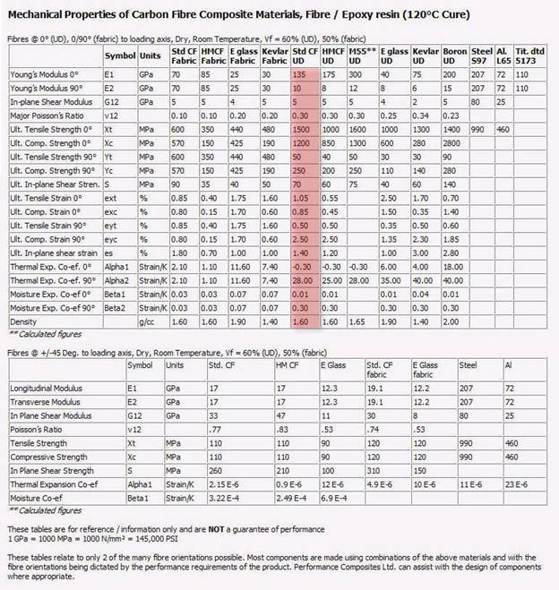
Figure 7 - Mechanical Properties of
Carbon Fiber Composites